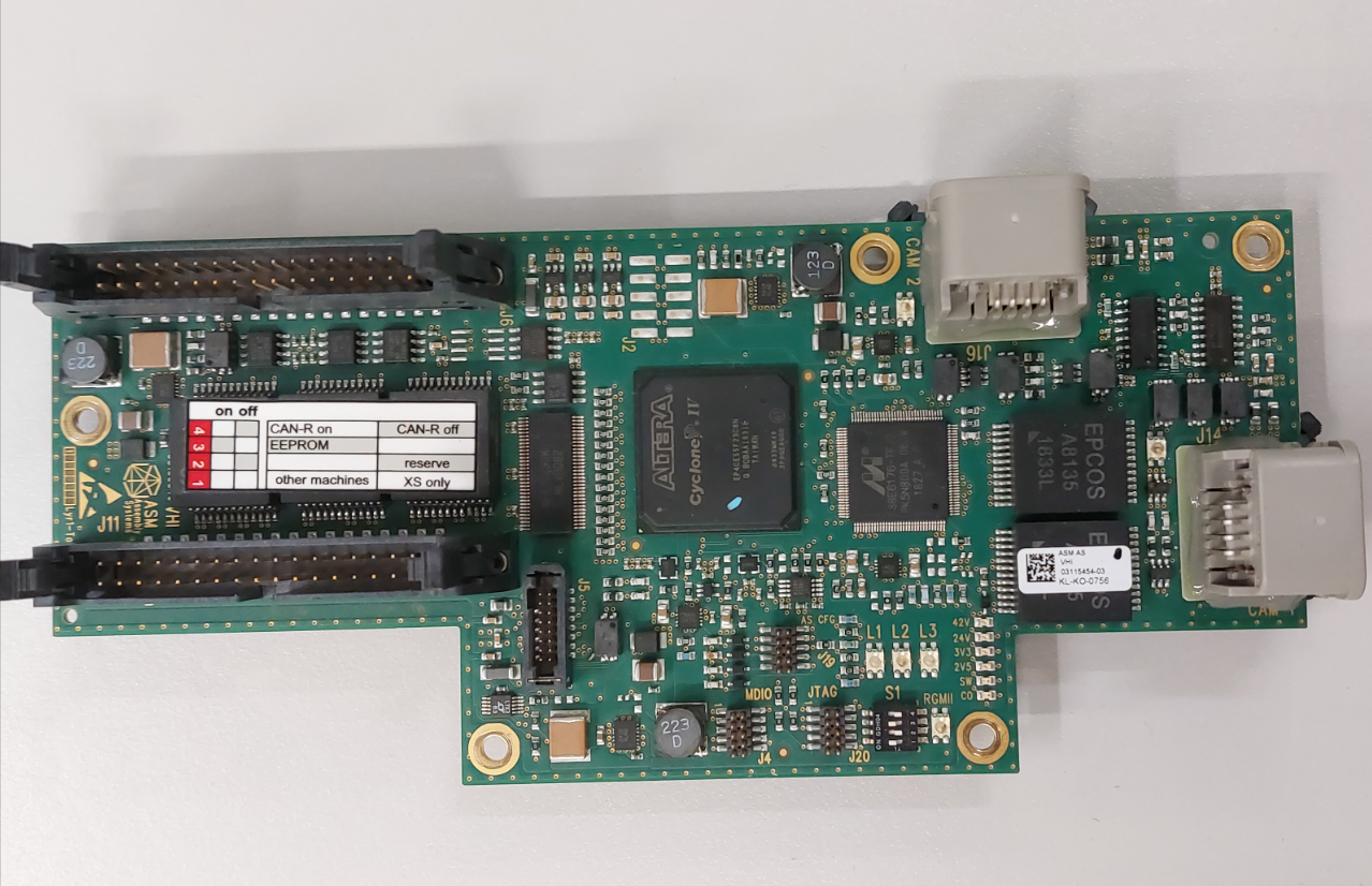
 Problema di errore: la connessione tra la scheda di interfaccia GIGE nel computer e la telecamera componente è interrotta.
Sblocca i segreti di una manutenzione efficace:I consigli dei nostri esperti per la risoluzione dei problemi degli accessori per montatori ASM
Mantenere le massime prestazioni del montatore ASM richiede una profonda comprensione del suo intricato funzionamento. Quando si tratta di risolvere i problemi con gli accessori, È fondamentale avere un approccio chiaro e logico.
In questo caso di manutenzione, Abbiamo identificato un'interruzione della comunicazione come causa principale del problema. Per risolvere questo problema, avevamo bisogno di individuare l'IC responsabile della comunicazione. Utilizzando il manuale dei dati per valutare i due chip canbus (82C251Y) accanto alla porta J6 del connettore, Siamo stati in grado di determinare se funzionavano correttamente.
Un altro componente chiave da considerare durante la risoluzione dei problemi è l'IC della logica di comunicazione (W262J) accanto alla porta J9, che controlla l'ingresso della scheda di controllo LED della telecamera componente. Capire come funziona la trasmissione dei dati dell'immagine attraverso la porta J14/J16, Il filtro della rete di comunicazione (EPCOS), il chip di elaborazione delle immagini DSP, e il porting J11 sul PC, ci ha permesso di diagnosticare e risolvere rapidamente il problema.
Mentre l'alimentazione e i segnali di comunicazione canbus attraverso la porta J5 sono importanti, Non erano al centro della nostra indagine. Adottando un approccio mirato e completo alla manutenzione, siamo stati in grado di ripristinare il funzionamento degli accessori per montatori ASM in pochissimo tempo.
Non lasciare che i problemi con gli accessori del montatore ASM rallentino la tua linea di produzione. Collabora con noi per ottenere suggerimenti di esperti e soluzioni per la risoluzione dei problemi che manterranno le tue apparecchiature in funzione ai massimi livelli di prestazioni.
Spieghiamo la definizione dei pin della porta di input e output dell'immagine:
J11 (40spilla): Porta di trasferimento dati immagine.
Spillo4/10/16/22/28/34:DGND.
Spillo1/7/13/19/25/31:DGND.
Perno 2/3:GIG_LINE_00N/P.
Perno 5/6: GIG_LINE_01N/P.
Perno 8/9: GIG_LINE_02N/P.
Perno 11/12: GIG_LINE_03N/P.
Perno 14/15: GIG_LINE_04N/P.
Perno 17/18: GIG_LINE_05N/P.
Perno 20/21: GIG_LINE_06N/P.
Perno 23/24: GIG_LINE_07N/P.
Perno 26/27: GIG_LINE_08N/P.
Perno 29/30: GIG_LINE_09N/P.
Perno 32/33: GIG_LINE_10N/P.
J5 (16spilla): alimentazione e comunicazione.
Perno 1/2/3:42V.
Spillo4/5/6:DGND.
Perno 7/8:PORTAL_ID0/ID1.
Perno 9/10:TRIGGER_HCU_P/N.
Spillo11/14/16:DGND.
Perno 12:24V.
Perno 14/15:MCAN_L/MCAN_H.
J1/J9:Porta di controllo della scheda di controllo LED della telecamera PCB/elemento.
J14/J16: componente / Porta di trasferimento dati dell'immagine della telecamera PCB.


 Problema di errore: la connessione tra la scheda di interfaccia GIGE nel computer e la telecamera componente è interrotta.